After some initial problems with the installation of my Flint Tip Tanks Spiders really came through. They paid for the cost of Cessna’s testing on the tanks after the cavitation issue. All is well.
I have since used them at least 10 times in my travels. The tanks have worked flawlessly and it’s lovely to have the extended range.
One note of interest is that it takes 23 minutes to pump each tank dry, this is a far better way to measure the fuel in the tank than by the gauges. When the tank is being pumped into the main you put the fuel selector on the opposite tank than the one you are pumping into.
Brent McAleese from Spiders was kind enough to take and edit the pictures below, along with an explanation of each photograph.
Flint Kit:
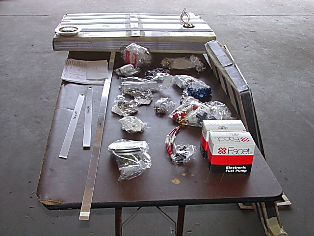
The flint kits come packaged with just about everything needed for installation - this also includes wiring that is not in the pics.
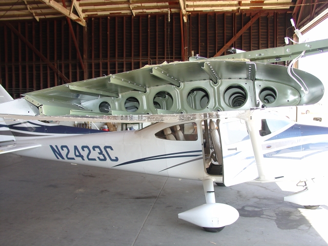
Outboard Rib
Since the tanks are installed by sliding into the wing tips, the outboard ribs need to be removed. Cessna has sure done a good job of priming all surfaces on their new planes.
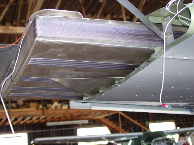
Installing Tank and Aids
The tanks are slid in with a little prying and banging and poking. The panels of sheet metal on either side help in sliding the tanks over stringers, rivets, etc.
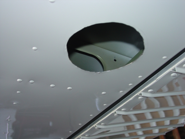
New Access
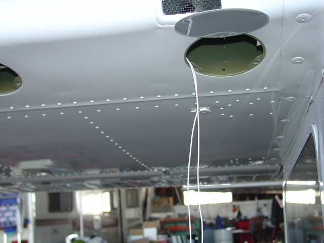
An additional access panel needs to be cut into each wing in order to install the fuel lines from the tanks to their pumps.
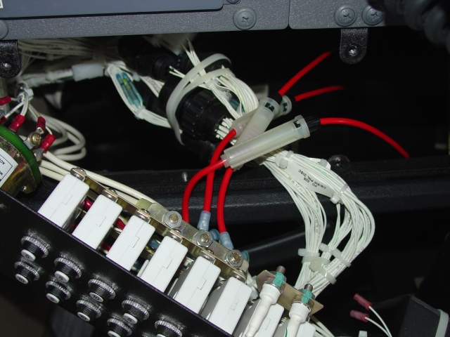
Fuse Holders
On older Cessnas the circuit breakers can be reached from behind the instrument panel On newer Cessnas the circuit breakers have a plastic cover over them. The only way to remove this cover is to remove the breaker assembly from the front of the panel. In the pics there are three fuse holders installed. Flint provides three, and these were installed while we were waiting on the fourth one to come in. Once the fuse holders were installed a hole was cut into the back of the circuit breaker assembly cover and the fuse holders were routed through. Two of the fuse holders are on Bus 1 and the other two are on Bus 2.
Wire Installed
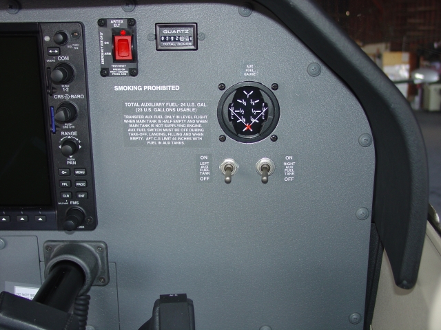
There are two wires that need to be installed in each wing. One wire goes from the fuel float to the fuel gauge and the other from the fuel pump to the fuel pump panel switch. The float wire runs completely along in front of the forward spar while the one for the pump only runs half way. Both wires are routed into the cabin, down along behind the panel in front of the doors, and then forward to the instrument panel. The right wing wires are fairly easy to run since the gage and switches are on that side. The left wing wires need to be routed across the cabin behind the instrument panel. Three additional power supply wires are, of course, ran from the fuse holders to the switches and gauge. The last spare wire was coiled up and tie wrapped behind the pedestal. The nice thing about a newer Cessna is that there is not 30 years of accumulated dust and dirt falling on your face when installing the wires.
Panel Layout
As much as I’d like to tuck the gage and switches as close together as possible, there is a lot more to them then what is seen. In short, the components need to be separated to prevent physical interference with each other and the panel coaming. The hole for the gage is cut out by using a two piece die drawn together by a large threaded bolt. An initial hole is drilled in the panel. The die is then separated and place on either side of the panel centered on the hole. The bolt is threaded through the die halves and hole and turned. As the bolt is turned the dies are pulled together and literally punch out the hole for the gage. An instrument overhaul and installation shop at Gillespie Field, Instrument Overhaul, lets us borrow the die.
Fuel Pump
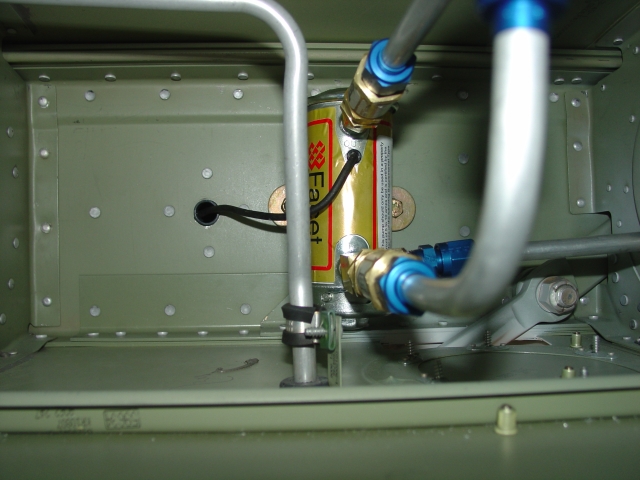
The fuel pump in each wing is attached behind the forward spar right about where the wing strut is located. These pumps only pump fuel from the aux tanks into the main tanks.
Fuel Lines
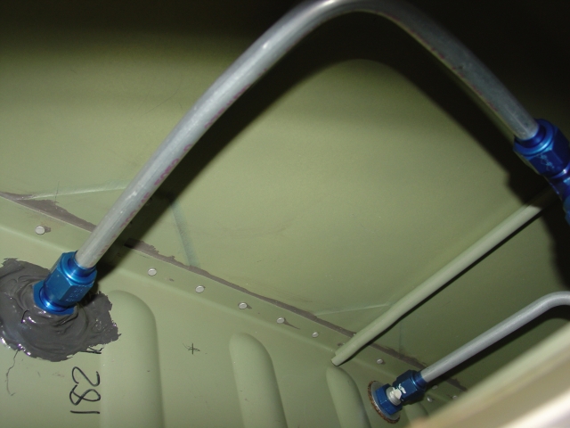
Nothing extraordinary with these pics. Just thought someone might like to see how the lines are plumbed into the main tanks.
Aux Drain
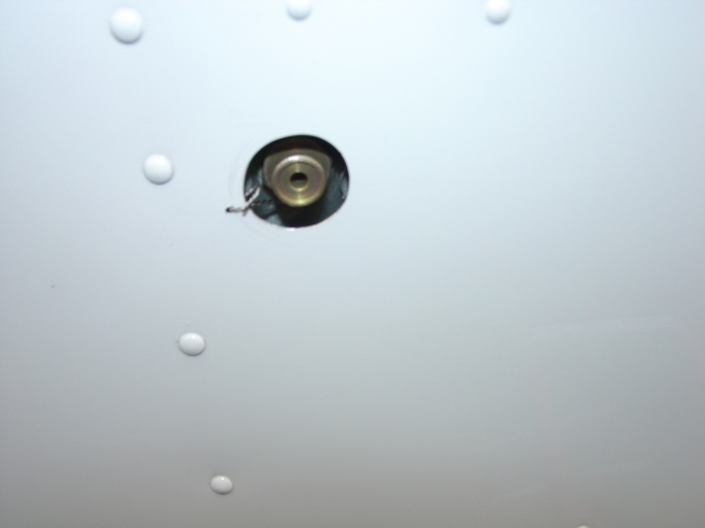
A hole needs to be drilled into the lower skin, obviously, for the aux tank drain. What is not seen in this pic is the number of drain holes drilled into the skin in case the tank leaks.
Fuel Cover
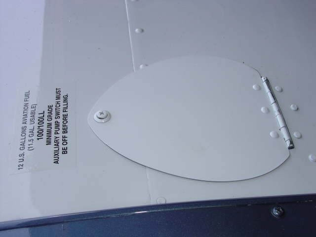
This is about as much of the aux tank the pilot is ever going to see.
